Below is my workbench or what I refer to as the GBSW Shops. This is where I do all of my DCC/Sound installs, Build and certify Rollingstock, modify turnouts and read my Railroad magazines.
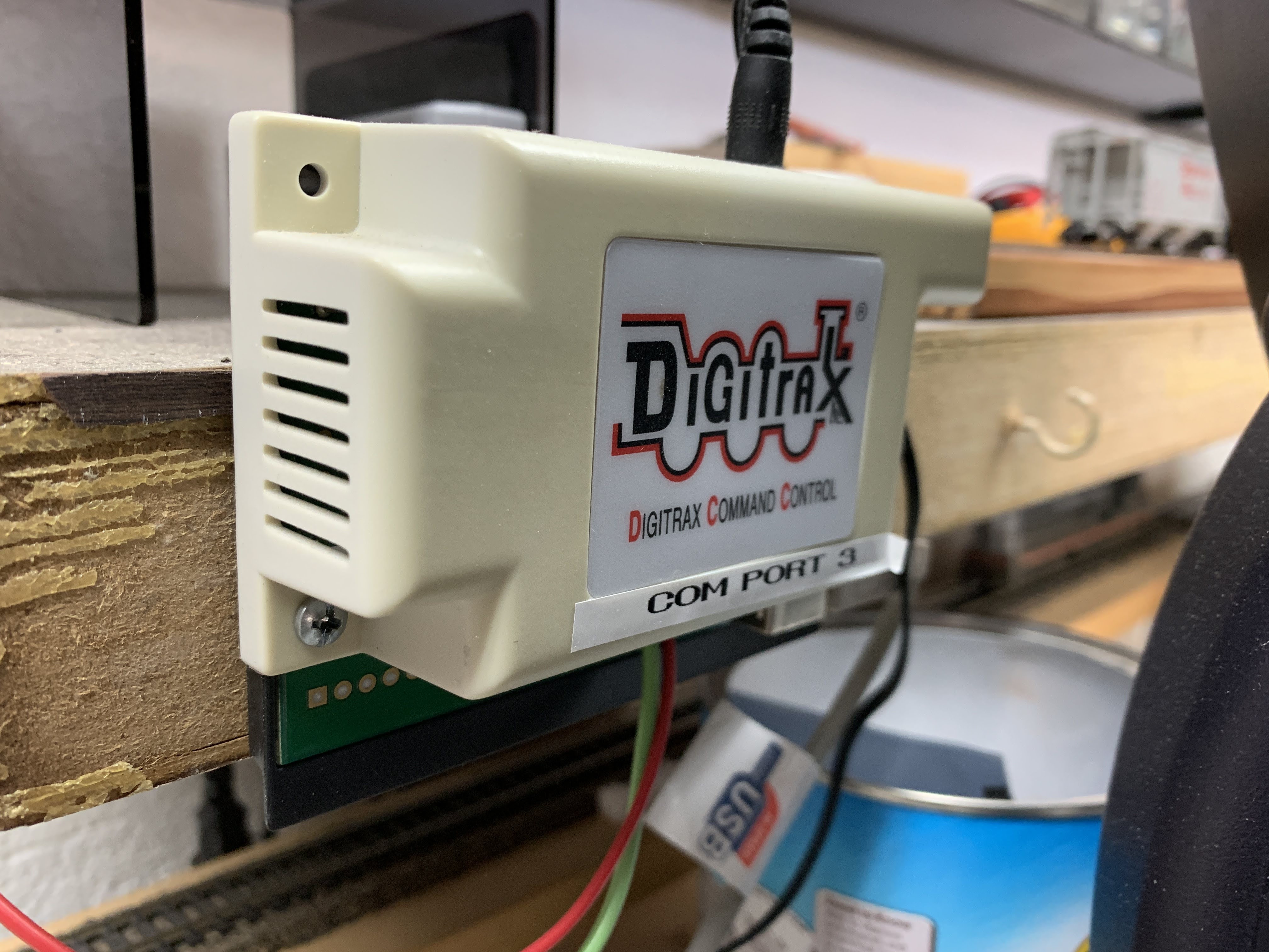
My set-up includes a test track which is enabled for either DC (Analog) or DCC or Digital Command Control so I can run either depending on the locomotive I'm working on at the time. There is a computer for researching weathering and detailing projects and also has JMRI's Decoder Pro installed on it with a Digitrax PR3 interface for programing of new DCC/Sound installs and for speed matching. A Xrtronics soldering iron does all my soldering work and the tools I use the most are with-in arms reach.
What I so enjoy is coming into my Train room, turning on my music be it The Great American Songbook, Rock & Roll, Classic Country or what I've been listening to of late, 60's music. It gets pretty busy here from time to time but is a great place to lose myself. The layout is to the right of these pics so all I have to do if something needs attention is run it over to the work bench and do what I need to do.
In the first pic, I have several projects going on, the first of which is a DCC/Sound install for an Athearn Denver & Rio Grande Western SD40T-2 and 2 pieces of rollingstock that need certification. And yes, I get burnt out from time to time doing DCC/Sound installs as this, for me, is very tedious and focus demanding work but the rewards are many and I always come back to this part of the Hobby because it is so rewarding.
My workbench or the GBSW Shops
My Digitrax DCS-100 and MRC Tech 3 Model 9500 analog transformer for the running of analog or DCC equipped locos
My Digitrax PR3 computer interface that talks to my computer & JMRI's Decoder Pro when programing a locomotive
A Digitrax DT402 throttle for the test track
ELEVATIONS My latest update as of 7/17/2020 shows what has been done so far. Both approaches to Arnold Yard have been elevated and leveled. The staging has been installed and it's approach from the mainline installed and is ready for track. The splices have all been installed. The Yard lead has been elevated and leveled. I am now in the process of painting the plywood an Earth tone color to match the ground caver. I will soon be finished with the painting of the plywood and will begin laying track soon and hopefully running Trains by Fall of this Year!
The grade for the eastern approach to Arnold Yard is set. All that is left to do for this approach is securing the risers to the joists. It took a while to get the grade dialed in as I was wanting to keep it to a 1.2% grade as the plan specified and this is a prototypical grade as the real Railroads try to stay away from anything more than 2.0%. Perfect! One more thing I discovered I want to do is level the roadbed (plywood) as it is slightly off kilter. I'll do this by making small shims from 1"x2" strips of wood and placing them between the riser and underside of the plywood. This way I'll have a perfectly level roadbed and no leaning locomotives or rollingstock. Instead of doing what I've done in the past which was to make a slot large enough to accept a 7/16 inch bolt that I would bolt the riser to the joist with giving me the ability to raise or lower the elevation as needed. I also made a cleat the width of the riser and screwed this to the riser. This worked very well but was very time consuming making the slots in the individual risers and making and adhering the cleats to the risers. So this time around I simply worked the riser up or down until I got the correct grade which in this case was 1.2%. I would then clamp the riser to the joist then drill and screw a 1 5/8 inch drywall screw up through the upper corner of the riser and into the 1/2 inch plywood. This made for some very sturdy roadbed and made doing this task much easier. When I last did this on my first Brooke Valley, I was living at our other house and there was a wall on three sides of the layout making this task very laborious.
A shim wedged under the plywood to level the roadbed
The Eastern approach to Arnold Yard
Working my way towards the camera
That's Arnold Yard in the background
The 1.2% grade has been set so stay tuned as there is more to come!
3rd Planit-A Virtual Tourwww.eldoradosoft.com I've been using 3rd Planit now for about 10 years and have found it to be instrumental in the Model Railroad trackplan design phase. The pictures below depict how the layout looks on 3rd Planit. Granted, it took several sessions of the Master Training 3rd Planit offers it's customers to get the plan the way I wanted but it was worth the time and money. Some of the goals I was wanting with this layout were:
1.) 26" radius curves (Ended up with 29.5 inch radius curves!)
2.) ATLAS #8 Turnouts for all passing sidings
3.) Better clearances
4.) A re-designed Yard
5.) Design for operations
I feel I accomplished these goals and then some but time is the real judge as I really won't know how well these improvements will work until I start running Trains. Stay tuned!
The layout with scenery - Virtually
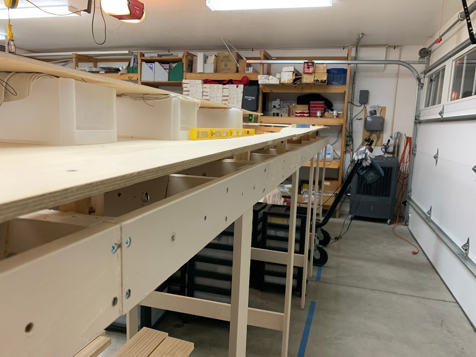
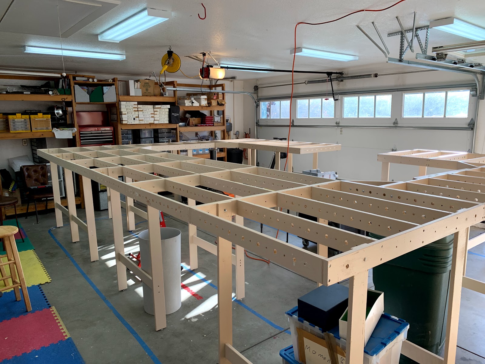
This picture shows the detail of the grid benchwork
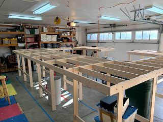
Siever's Benchworkwww.sieversbenchwork.com Siever's Benchwork is something I have known about for over 30 years. I always built L-Girder benchwork in the past but had done this method so many times that this time around I was looking for a different way. I ordered the Benchwork from Siever's who was very helpful in answering all my questions and addressing my concerns. Siever's even took my dimensions and put together the sections on paper how everything could go together and this, by the way is how I did it.
The Benchwork plan as put together by Siever's Benchwork
These are the Siever's legs sets and different size sections that make up the whole
It took about a day and a half to put all this together saving me a ton of time
It took 3 days to assemble all of the Siever's benchwork, all 18' x 13' feet of it!
The finished product!
Baltic Birch Plywood While working with Randy Phiffer of 3rd Planit software on my trackplan, Randy recommended I use 1/2" Baltic Birch Plywood since it is 9 ply vs 3 or 4 ply of normal 1/2" plywood. So I took the plunge and ordered this from the Lowes in Palmdale, CA. Turns out Lowes would deliver this to my House for a nominal fee saving me a lot of grief. At $56.00 for a 4'x8' sheet, it's not something I would buy everyday but for this purpose, as I would find out, it was worth it. This plywood seems to be much easier to work with and to cut. Being that it is sanded on both sides with a very minimal amount of knot's, I was very pleased as to how well this plywood worked out. Cuts had very little splinters and the cuts were much smoother compared to normal 1/2" plywood and it's strength compares to that of 3/4" plywood.
12/7/2020 Update:
This plywood is amazing as it is much more durable and rigid for a model railroad. It is much smoother than regular plywood as well and it grips track nails much better. Another thing I like about this plywood is that over a span between risers, this plywood will flex but not like normal plywood, allowing the driving of track nails to be much easier. For the cost you would spend on 3/4" plywood, at about the same cost and at only 1/2 inch, Baltic Birch is the way to go as the 9 ply of Baltic Birch makes a BIG difference!
December 21, 2019 and Delivery Day has arrived!
Time to go to work
The finished product
The Trackplan With the Benchwork made and the plywood secured to the Benchwork, it's time to start laying the trackplan down onto the plywood. This is down using Randy Phiffer's (El Dorado Software) 3rd Planit model railroad design program. I printed out the design via 8.5"x11" sheets which had markings on them to indicate where and how each sheet should go. This process took about 2 months to complete and included along the way some mistakes that I overcame such as the printed sheets didn't always line up like they should had. But thru perseverance I was able to overcome these obstacles. I believe this is what I enjoy most about Model Railroading. It presents problems that I must overcome via ingenuity. You can take a look at the trackplan here. Bear in mind this diagram is not to scale but will give you an idea as to how things look.
This and the pictures below show the trackplan as it was being laid down onto the plywood
Cookie Cutter
Cookie Cutter is one of several methods used to gain elevation for track, scenery, structures and other elements of a model railroad. I had marked with a thin red marking pen where I wanted to make the cuts and checked several times before making the cuts knowing that once I started cutting, I was beyond the point of no return. It took all of 2 days to complete the cookie cutter using the method shown below and I am very happy with the results.
Let me add that when doing cookie cutter, it WILL kick up a lot of dust so be sure you wear eye protection and a mask to protect from breathing or getting dust in your eyes.
5/13/2020
The lifting or elevating of Arnold Yard and it's approaches has begun! I installed 1"x 2" risers on the back of Arnold Yard and supported the front portion using a 4"x 4" and a 2"x 2" stacked on top of one another. This gave me the exact height I needed which was specified by the plan. Doing it this way would enable me to place the staging under Arnold Yard without any risers getting in the way. Tomorrow I will continue with the elevating of Arnold Yard and it's approaches.
The lifting of Arnold Yard has begun
My Beautiful Wife Arlene standing next to the elevated Arnold Yard
My jigsaw and Rockwell SoniCrafter getting it done!
That's me doing the cookie cutter
Using the Jigsaw to make the main cuts for the cookie cutter
SPLICE PLATES
Once the cookie cutter was completed, I needed to bring together the different pieces of plywood to enable a smooth transition from one piece of plywood to another giving my Trains a smooth ride. This was done by applying splice Plates where two pieces of plywood came together. I first had to figure out how to make a template that I could transfer onto the splicing material which is 3/8th's inch plywood. I accomplished this by using a roll of 18 inch wide paper I was given by my good Model Railroading Friend Lois Kroll. I used a Sharpie permanent marker to trace out where the shape and size of the template would go directly onto the 1/2 inch plywood. This would make it much easier to see and trace out the splice using the roll of paper. Once I did this, I cut out the template using a pair of scissors, then laid and tapped this template to the splicing material and traced out along the edges of the template. Then it was just a matter of cutting out the splice plate using my Jig Saw making sure I cut along the inside of the line I scrolled from the template as this would ensure a nearly perfect fit for the application at hand.
I would then glue and screw the splice plate to the under side of the 1/2 inch plywood making sure there were no gaps between the splice plate and the plywood. Use a good Carpenter's Glue such as Elmer's and a putty knife. Use the glue sparingly and spread it using the putty knife ensuring that the entire surface of the splice plate get's covered with the glue. This minimizes drips and makes clean-up much easier. And be sure to have a wet rag or two handy for drips and a dry cloth to wipe away moisture off the plywood or any other surfaces you don't want moisture on.
Also, be sure to have a couple sticks of wood (I used a couple of pieces of scrap 1/2" by 1") to place on each side of the splice plate once you have glued and screwed it to the under side of the 1/2" plywood as this will prevent any adhering to the bench-work of the splice plate. Do this immediately after you completed installing the splice plate because once that Carpenter's glue dry's, it'll be extremely difficult to separate the splice plate from the bench-work! Ask me how I know.
To screw the splice plates to the 1/2 inch plywood, I used a #6-9 x 1" course drywall screw purchased from Amazon. I found that the Big Box Stores didn't carry anything smaller than a 1 5/8th's drywall screw but found Amazon had a good selection of the smaller size screws. The photo's below illustrate what I did to make the splice plates.
Notice the outline of the Sharpie pen used to make the template. The other lines you see running diagonally are for a template made for the mainline that runs underneath
Tape the roll of paper to the 1/2" plywood and trace out the line made from the Sharpie pen
Photo showing the actual splice plate
The outline from the Sharpie is very easily seen through the paper used to make the template with
Make sure you don't have any gaps around the entire splice plate
Where there will be separate elevations, I used one splice plate and will come back after the glue dry's and cut the splice plate where you see the line. This save's time and a lot of hard work.
Another example of using one splice plate to accomplish separate elevations


No comments:
Post a Comment