Some resources you may find helpful in your endeavors:
Athearn Maintenance and Upgrade: Applies to most any Manufacture. I have found in my experience that you can forego this step with most locomotives but with some, there's no getting around it so best to take the time and do what a Model Railroad has to do, you'll be glad you did.
DCC Check List: I have a checklist I use to to help me remember to do certain things. It can be had HERE.Please make a copy of this first by clicking on File/Make a Copy. This prevents editing of the original form and this way, you can customize this for how you like it. CTRL+P will print out a copy of this for you to use.
4/3/25 Athearn Union Pacific DDA40X 6925
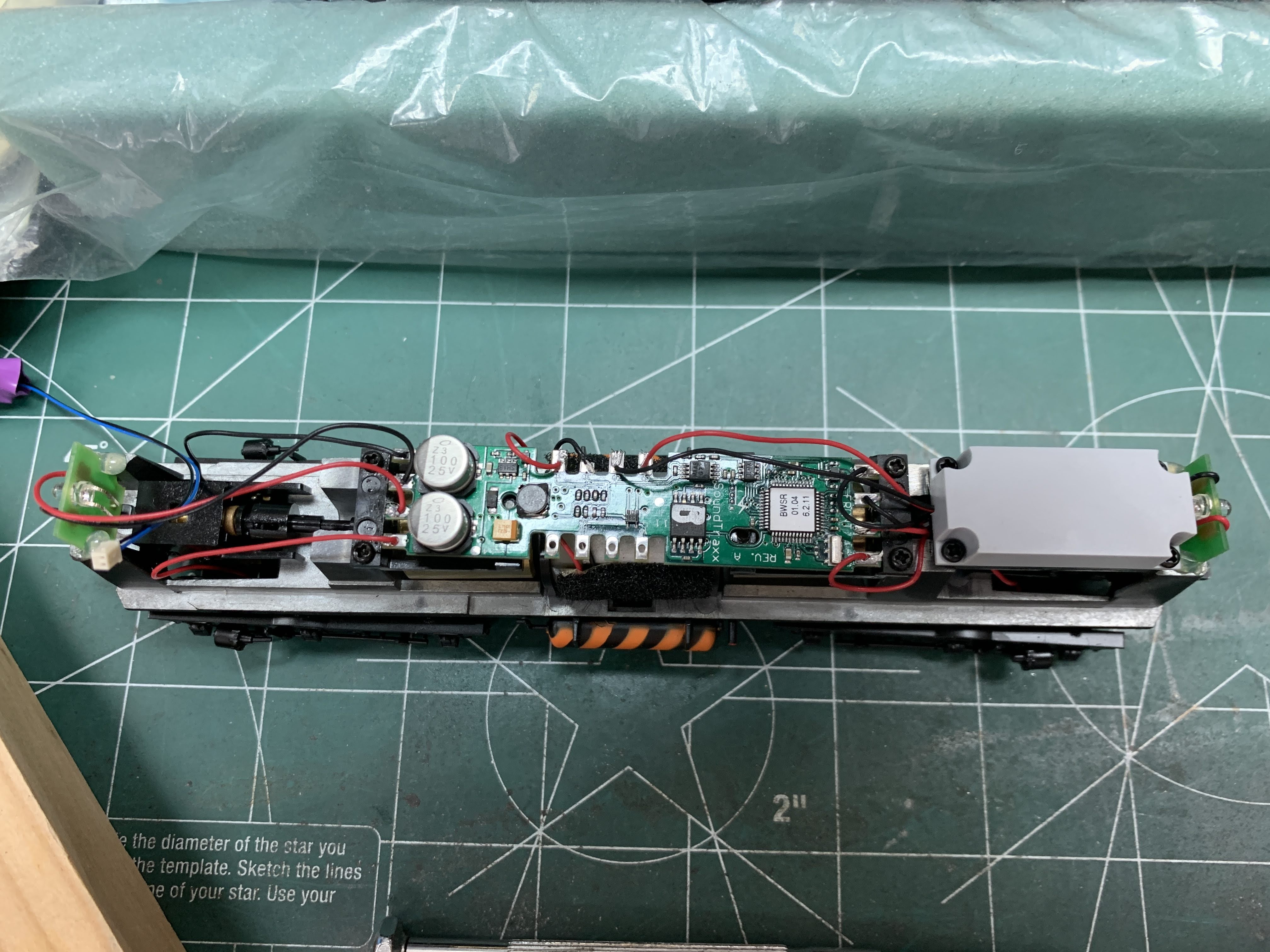
Union Pacific DDA40X 6925 with a new Tsunami TSU-PNP8 decoder
This locomotive came with a 2011 SoundTraxx Tsunami Decoder on the forward motor and what look like a Decoder for the rear motor but can't say for sure what this was. See picture below.
Decoder on left was for the forward motor
I contacted an installation service to inquire about having them do the work on this loco but after letting them know this was a dual motor loco, I never heard back from them. I then reached out to SoundTraxx who suggested using a TSU-PNP8 2 amp decoder. These decoders are made for HO and S Scale locos. I needed to do a stall test to determine if weather this decoder could handle a dual motor loco such as this. The loco pulled 1.75 amps on stall and .75 normally. I thought for normal operation this should be ok.
SoundTraxx Tsunami 2 TSU-PNP8 2 amp Decoder Product Number 885813
Make sure when you order this decoder not to order the EMD Diesel-2 Product Number 885824 version but rather the EMD Diesel Product Number 885813 as the EMD Diesel-2 does not have the sound file for a dual motor Locomotive such as the DDA40X.
I figured if I could get this loco to run with Analog (DC), it should run in DCC as well so I drew up a Dope sheet thinking it should run in DC or DCC wired the same way. See pic below for this drawing.
Dope sheet for how I wired this loco
The thing to remember is that this loco's rear motor is turned around opposite from the forward motor so, the track feeds coming from the rear truck must be reversed as seen on the drawing. It took me a while to let this sink in because I'm used to wiring my track feeds to the Decoder Red on the Engineer's side and Black on the Fireman's side but do it this way with this Loco and you will experience a short. Same for the wires coming from the rear motor, they must be reversed or you'll have a Short. Something to remember.
As I had thought, this loco ran great once I wired it as shown in the drawing. One thing out of the way, now time for the Decoder but first, I wanted to change out the speakers. I installed two SoundTraxx Round 30mm Speakers Product number 810114 and they sound great!
SoundTraxx 30mm Round Speaker
With that out of the way, it's time to dig into installing the Decoder being mindful of the drawing and how the track feeds from the rear truck and motor leads from the rear motor must soldered to the Tsunami board. If you do mis-wire these, no worries as the Decoder has a built in circuit breaker to shut the Decoder off but don't wait too long to remove the loco from the track or you will burn out the Decoder. Ask me how I know.
Something I did to eliminate wire breakage was a short piece of 3/8 shrink wrap around the solder joint on the Decoder. Before you solder the wire or wires to the Decoder, cut a short piece of 3/8 shrink wrap and slip the wires through it and make your solder, then slip the shrink-wrap over the solder joint and hit it with your soldering iron. This helps support the wires and prevent or reduces the chance of them breaking off.
Once I got the Decoder installed, it was a matter of some wire management and taking it for a test drive. Take your time putting the Body back on these. I placed the loco upright on a solid surface, lined the body up as best I could in relation to where I thought the body would sit on the chassis then slowly and I mean slowly rocked the body using lite pressure to push down. As I did this, I stopped, checked for any wires sticky out and made sure the trucks swung freely then continued to rock and push ever so slowly until the body settled onto the chassis. It was kind of like those pictures you see in the Railway press of a Loco being lowered unto it's chassis at the EMD or GE Erecting Shops. And make sure not to push down on any details such the radiator fans as these are very fragile.
So I finally get everything put back together and things run great during the Test Drive until 6925 stalls on a turnout. This is usually caused by a bad track feed some where, usually on a truck. An easy troubleshooting method is to lift one end of the Loco while it is running, if the Loco continues to run set it down then lift the other end. If it stops running then there is a bad feed coming from that truck. I removed and took apart this truck and found the Black wire had an open in it. An open in case your wondering, is a break in the wire preventing electricity from flowing. I replaced this wire and it ran like a charm with no stalling over any turnouts. Now hopefully it's just a matter of programming 6925 but I have to wait for my new Digitrax PR4 to arrive for this to happen but that's another story.
P.S. One more thing I forgot to mention. When your securing the Body onto the chassis, I found what worked best for me was to install the couplers first. Two reasons for this the main one being if you install the chassis and fuel tank screws first, this eliminates any wiggle room thus making it difficult to install the couplers. Secondly, it can be a chore getting the Body off one of these Behemoths should you need to remove the Body for any reason during this phase. Once I got everything dialed in, I then went ahead and screwed in the Fuel Tank and Chassis screws. Hope this helps!
6/21/22 Broadway Limited Imports HO Scale GP-20
BLI went out of it's way to ensure the detailing was right for this model, they really did their homework. Unfortunately, BLI neglected to do it's homework when it came to the sound for this locomotive as the GP-20 came from the Factory with a turbocharged 567 Diesel Engine in it. BLI's version comes with a non-turbocharged 567, essentially a GP-9. Now this would be OK as the GP-20 looks very much like a GP-9 and since the Southern Pacific owned some low nose GP-9's, one could, after changing the number, pass these off as GP-9's. But if you model Santa Fe or Union Pacific who, to my knowledge didn't have any EMD built low nose GP 9's then you'll need to read on to change out the GP-9 sound for GP-20 sound.
The Paragon 4 decoder BLI installs in these is a cantankerous beast with wires running everywhere and when you turn these on, no matter if you turned everything off from a previous run, all the lights go on and these come with a LOT of lights. Number boards, class lights, Pyle lights, front and rear headlights as well as cab lights and they all come on when you turn the track power on every time! UGH!
A BLI Paragon 4 Sound Decoder
So if your like me and want your BLI to have GP-20 sound with reliability and ease of use then follow along with me while I show you how I installed a SoundTraxx 21PNEM8 Decoder using a Decoder Buddy V5 board from Nix Trains. It's not hard at all to do and you'll have the pride of having done this yourself. So let's get started.
Before I go any further, let me warn you to be very careful handling your loco as it has many fine details including the fan screens which, by the way, are brass and can be distorted or break off very easily especially when removing or putting back on the shell, so be careful!
First start off by removing the shell. This is an easy task as you'll flip the loco to expose it's under belly and using a Phillips screwdriver, remove the two screws holding the couplers in place then remove the couplers. Next, if you look towards the rear of the loco, you'll see two tabs that grip the chassis. Take your blade screwdriver and pry ever so gently on these tabs and the body should slip right off. Be careful to have a firm grip on the chassis and body when doing this.
Cut the wires from the connectors shown in the picture above
Next is cutting off the connectors on some of the wires so you can solder these to the Decoder Buddy later on. I know this sounds like your destroying a perfectly good locomotive but trust me on this one. You need not do this to all the wires as I will show you. First, remove the connectors from the decoder for the front and rear track feed wires and cut these off. These should be a Grey and White wire for the front track feeds and a brown and black wire for the rear track feeds. See the above photo to help you with this.
Now look for the Motor wires. These should be Yellow (+) and Blue (-). Remove these from the decoder and cut off the connectors. Now look for the speaker wires which are Red and Grey and cut off the connector. This takes care of the connections for the chassis. Don't concern yourself with the many jumper wires on the Paragon 4 decoder as these are just fluff and have nothing to do with the new decoder install.
Next are the connectors for the wires coming from the shell or body. Follow these to their respective connectors and cut these off. These feed the lights and need to be ID'd once we get these situated. This is probably the hardest part of the install but needs to be done to make sure the lights work as they should.
Also, keep in mind you don't have to hook up all the lights like I did. If your a Santa Fe or Union Pacific Modeler for instance, then you only need to do front and rear headlights and maybe a Beacon, your choice. Cut off the connectors as shown in the picture above.
The Decoder Buddy installed with the pick-up, motor and speaker wires soldered to it
A side view of the V5 Decoder Buddy
Now it's time to remove the old decoder and install the Decoder Buddy board. I situated my Decoder Buddy so the connector board was towards the front of the loco. This would place the new 21 pin decoder about the middle of the loco where there's a little more headroom. You'll notice the Decoder Buddy fits perfectly where the old Paragon 4 decoder use to sit, SWEET! Secure the Decoder Buddy with the screws making sure not to over tighten these.
The Decoder Buddy I used for this install Decoder Buddy V5 Board
Our next item of concern is to I.D. the wires coming from the shell as this will tell us which wire/s go where. Below is a dope sheet of these wires I made for my application. Your wires will most probably be the same but better to check and make sure just in case. Using a 1.5v AAA or AA battery, go to each set of wires shown below and check to see if they light up. This will also indicate which lite does what i.e. front headlight, cab lite, Pyle lite, etc. Now I know your excited and can't wait to hear that EMD Turbcharged 567 sound but your almost there and this doesn't take as much time as you think so take your time here and make sure it's right.
Front Lites:
Red & Black = Front Class Lites
Grey & Black = Front Headlite
Black & White = Cab Lite
Black & Red = Number Boards
Black & Grey = Pyle Lite
Rear Lites:
Red & White = Class Lites
Red & Green = Pyle Lite
Red & Brown = Rear Headlite
Red & Black = Number Boards
There are about 7 common wires for just the front lights. What I did which I later found out I didn't need to do, was tie all the common wires coming from the front lights to a larger wire. This made it much easier to solder a single wire to the soldering pad rather than a bunch of wires but since the Decoder Buddy V5 has 2 rows of soldering pads on the connector board for the common wires (U+), it makes for an easy job as you just solder a single wire to each U+ pad on the connector board. Lessons learned!
Since BLI has all the wires for the rear lites going to a single board at the back of the loco, there is only one common wire coming from the rear lites making this very easy. Just check each wire against the rear common wire to determine which wire dose what i.e. Pyle lite, rear headlite, etc. then solder these to their respective pads on the connector board.
Solder the pick-up wires to where it says "Track A" and "Track B" on the decoder Buddy making sure not to transpose these wires. The speaker wires can be soldered onto the two middle soldering pads at either end of the Decoder Buddy but be sure if your doing two speakers to make sure the polarity of these wires are correct i.e. red to positive and black to negative. If your using a single speaker, it doesn't matter but I make it a habit to go red to positive, black to negative so if I ever do do two speakers it'll be right.
Next, solder the yellow and blue motor wires to their respective soldering pads on the Decoder Buddy making sure yellow goes to positive and blue goes to negative. How can I tell which wire is which? Look at the motor and you'll see the yellow wire coming from the top of the motor which is always positive and the grey wire coming from the bottom of the motor which is always negative.
The function wires are soldered to the connector board with the front A0f (usually Yellow) and rear A0r (usually White) headlights soldered to A0f and A0r respectively and any other function wires to A1, A2 , A3, etc. All common wires are soldered to the U+ soldering pads on the connector board.
Once you have soldered all the wires to the Decoder Buddy making sure everything is secure, now is a good time to remove any residual soldering flux off the Main board and Connector board. Do this by wiping these areas off with a QTip swab soaked in ISP Alcohol. Also, take a look now to see how you'll do any needed wire management since you have everything exposed.
Now that you have all the wires soldered on to the Decoder Buddy, you've cleaned off the boards and figured out your wire management, now it's time to install the new SoundTraxx 21PNEM8 decoder onto the Decoder Buddy and test it to make sure the loco works as it should. What I did with my last install was use a LokSound Decoder Tester to pre test and program my decoder. What made me do this is when I placed the loco on my program track with the 21PNEM8 decoder installed onto the Decoder Buddy, Decoder Pro couldn't find the decoder type which for me, is unusual as I rarely have a problem with this.
The decoder I used for this install. SoundTraxx TSU-21PNEM8 Decoder
So I installed the 21PNEM8 decoder onto the decoder tester and Decoder Pro still would not sense a decoder type. Usually when this happens, it indicates a broken pick-up wire but this wasn't the case this time. At any rate, I was able to go into Decoder Pro and manually set this decoder up, give it an address, set up my speedtables and function lights all while using the Loksound decoder tester. If you don't have a decoder tester, no worries as you should still be able to manually program the decoder while it is installed on the Decoder Buddy.
Photo showing where the 21PNEM8 decoder goes and where the Connector board goes
I tried installing a Broadway Limited Imports GO PACK as this seemed to be smaller than SoundTraxx Current Keeper. Unfortunately, this was a no go as there just wasn't enough room. No worries though as these locos have all wheel pick-up and have no issues running over my #8 ATLAS turnouts.
After you get your decoder programmed and everything looks good, take your install for a spin as now is the time to found out if something is wrong. Once everything checks out ok, do some wire management and ensure the wires coming down from the front of the shell aren't clumped up as this well prevent the shell from going on. Tuck these back and away from the front portion of the Decoder Buddy. When you reapply the shell, it may not look like it's going to go on. I had the same situation in that the shell seemed to not go on all the way but after playing with it for a while and even walking away from it, I decided to just see if it would go on and I could install the couplers and it worked!
WARNING!!!! This is where you need to be careful handling your loco because your pressing on the shell and could easily damage some details or the fan screens. So BE CAREFUL!!!
I hope this helps someone in converting their BLI GP-20. Nothing is set in stone and I lay no claim in any of this. I've just not seen any information on this so I thought it might help someone out there who is looking to do the same thing I have done. It's not hard, just takes some time is all. Thank You for your time in reading this article, I hope it helps you in some way.
5/25/2021
Bowser Southern Pacific Baldwin DRS 6-6-1500 #179
An update to my install of DCC and sound in this locomotive. The pictures below are of the finished product. The SoundTraxx Current Keeper most definitely makes a huge difference in compensating for the lack of all wheel pick-up in this locomotive as it no longer stalls while running over turnouts or at grade Railroad crossings. Pictures to follow.
5/15/2021
This is my first loco I have installed a SoundTraxx Current Keeper in. A Current Keeper or Capacitor Bank maintains power to a loco up to approximately 10 seconds on dead track or helps compensate for dirty track. I had purchased this loco last year and hadn't really had a chance to run it until recently. Come to find out, this loco does not have all wheel pick-up causing it to stutter or even stall while moving over some turnouts.
This isn't a game changer but it needs to be fixed so, I have installed a SoundTraxx Current Keeper #180140 which should go a long way in keeping this loco from stalling. I have ordered a 21 pin SoundTraxx Tsunami sound decoder and it should be here in a couple of weeks.
Another first with this loco is my using a Decoder Buddy Mini by NIX Trains. I like the Decoder Buddy Mini because it is pretty much the same thing as the larger v5 Decoder Buddy, the difference being the Mini is designed to enable removing the body without dealing with any wires that connect to the lights whereas the larger v5 Decoder Buddy uses a piggyback board that the lights and functions connect to so you can remove the piggyback board and remove the body for access for maintenance or repair. On my loco, the front and rear lights are built into the frame of the loco so no need for the larger Decoder Buddy.
The Decoder Buddy already has 2000K ohm resistors built into both the Larger as well as the Mini Decoder Buddy making installation of LED's a snap! I also replaced the OEM speaker with a RailMaster DS1436-8 speaker to give this loco better sound. Also, there was an issue with the horn not being very loud even when I went into Decoder Pro and MAXed this out, it still was not very loud so hopefully that has been fixed with what all I did here today. Stay tuned for an update when I install the new decoder.
This as well as the next photo shows the old installation of the OEM decoder and speaker
This photo and the next show the new Decoder Buddy Mini installed, the SoundTraxx Current Keeper and a new RailMaster speaker
Just waiting for the new decoder to come in!
DRGW SD40T-2 #5378
May 30 2021
Well, I think I'm pretty much done with this loco. Some programing and a couple of minor issues to resolve but over all, it's good to go. This loco has been punished repeatedly but it has hung in there knowing it would see the day when it would roam the rails again.
The video shows the installation of the Mowtown SMD (Surface Mount Diode) or LED's. These LED's come with the lens already adhered to the LED making it much easier to install. DRGW 5378 comes equipped with a Pylelight in the nose like the prototype and a Nathan M3 Horn like the prototype.
Lessons Learned:
-The MowTown LED's as with most LED's are polarity sensitive. Just think of a pair of battery jumper cables, red is positive and black is negative which is how the red and black wires on the LED's should go onto the Decoder Buddy Mini.
-Soldering a single piece of 1 inch 22AWG stranded wire to each pad of the Decoder Buddy for the motor + and -, track pick-ups, functions and the speaker makes soldering multiple wires to these so much easier vs trying to solder each individual wire to each individual soldering pad on the Decoder Buddy (see the photos below for May 15 2021).
DRGW #5378
DRGW 5378 with the MowTown Hobbies LED's installed
A couple of pics showing the back end of DRGW #5378 showing the installed MowTown LED's
May 15 2021
I have redone this install using a NixTrains Decoder Buddy Mini board and a SoundTraxx 21PNEM Tsunami 2 sound decoder. I thought I had the previous decoder which was a drop in type SoundTraxx Tsunami decoder dialed in but things just didn't work out the way I was hoping with this decoder. Chalk this up to lessons learned and boy, you never stop learning while doing this stuff.
I tried something different that seemed to work pretty good for me and that was soldering an inch long piece of stranded 28 AWG wire to the Decoder Buddy Mini for the track power, motor + and -, front and rear lights, any functions I want and the speaker. I then tinned the ends of each of these wires that was to connect to the wires coming from the chassis and the body. I then made a hook (SEE PHOTOS) with the tinned portion of these wires, making sure I slid a piece of 1/8th inch heat shrink tubing onto each of these wires before soldering them to their corresponding wires. This made connecting these wires much easier.
The Decoder Buddy will only accept a 21 pin decoder but that's just fine with me as everything SoundTraxx and LokSound makes also comes in a 21 pin version. I have only used SoundTraxx TSU-21PNEM sound decoders up to this point but with the versatility of the Decoder Buddy, it will accept any Manufactures 21PNEM decoder, sound or no sound.
Plus, the Decoder Buddy doesn't take up nearly as much room as a standard drop-in decoder. Just make sure you measure the vertical distance from where the body contacts the chassis to the top of the inside of the body as the pins on the Decoder Buddy are somewhat tall and you'll want to make sure your install will fit in the vertical space you have available. If you have to, the Manufacture says you can cut these pins but only as a last resort.
A simple way measure for the vertical clearance of a locomotive shell is to use the opposite end of a pair of Vernier Calipers and measuring from the end shown in the photo, take the loco body and measure from where the body contacts the chassis to the top of the inside of the body. Then take this measurement and gently place the end of the caliper on the chassis where the body makes contact.
I'll place the Decoder Buddy where I want it (usually on top of the motor) then, using the measurement I got from the calipers, I'll make sure this measurement is taller than the pins on the Decoder Buddy which usually is the case but it's always good to make sure. A little time spent doing this will save you a lot of time and grief on the other end. Ask me how I know.
Measure from the end of the calipers as shown
This photo shows where to place the calipers for measuring the vertical clearance
Where you see the main portion of the calipers resting on the body is where the chassis contacts the body
Taking this measurement, gently place the end of the calipers as shown, making sure this measurement gives you enough vertical clearance to accommodate your install
The hooks at the ends of the wires shown provide a much easier means of soldering all the wires from the chassis and body
Make sure to twist all your wires whenever possible as this make for better wire management
An overview of my latest install
Be sure to place a piece of 1/8th inch shrink tubing onto each wire before making any connections
January 2021
I purchased DRGW #5378 new about 10 years ago and it has been somewhat of a thorn in my side as it has never really ran well. When I got my Mainline installed on my current layout, 5378 just didn't do very well as it would derail and slow down considerably around the curves. This poor Locomotive needed help!
So, I tore it down and found several things going on the first of which was a melted worm gear housing clip receiver, the portion of the worm gear housing itself where the worm gear clip snaps onto had melted during a previous install and just noticed it this time around. This may well have caused racking of the worm gear since it wasn't being held in place on top the Bull gear correctly causing binding in the drivetrain especially around curves. This entire truck assembly got replaced with a new one and now it runs much smoother.
Though not the exact truck in question, this picture shows the clip receivers that had been damaged from a previous decoder install
This truck is not the damaged one but shows a broken worm gear clip receiver which makes this truck pretty much useless. Something to check when re-working these
I am always looking for ways to improve my installs and this install is no exception. I wanted to use the same SoundTraxx DCC/Sound unit my Friend had installed but also wanted to install better LED lighting using a method I learned from Mowtown Models seen here on YouTube.
The only issue I have with this method is my Hands are not all that steady and you must get that LED smack dead center of the lens or otherwise it either wont fit in the opening or not shine correctly. Now having done this, I will say if you don't get the LED exactly right on the mark, it will still work, it's getting the whole thing to fit in the opening that can be tricky.
Update: MowTown Models now offers these LEDS with the lens already glued to the LED making this part of the project MUCH easier. Check it out >>> HERE!
Twisting of the LED wires is very helpful with the wire management of all these wires and keeps things looking clean
Photo showing 1/8" heatshrink tubing being used for a conduit for the LED wires
Photo showing how I routed the LED wires for both the front headlight and Mars light
I wanted to install and route the LED wires in such a way to prevent them from being visible in the cab windows
I wanted a clean look of the headlight lens using the method learned from Mowtown Models
Lens installation shown from another angle
Note how the lens are flush and don't protrude from their base


Just watched your work on the electronics for your diesel locomotive. Very delicate work and a very nice job you have undertaken.
ReplyDelete